
2. Motors and Coordinated Motions#
All axes of the XRD end station are implemented as EPICS motors. Instruments like the slits or the table have pseudo motors implemented for coordinated motion.
The use of pseudo motors for coordinated motion is strongly recommended for day-to-day use.
2.1. Goniometer axes#
name |
purpose |
|---|---|
|
vertical 2θ |
|
vertical θ |
|
chi |
|
phi |
|
horizontal 2θ |
|
horizontal θ |
|
analyzer θ |
|
analyzer 2θ |
|
detector horizontal motion |
|
attenuator wheel |
|
scatter shield vertical motion |
|
sample X |
|
sample Y |
|
sample Z |
All of these motors can be moved using standard movement plans, e.g.:
RE(mvr(eta, 0.2))
RE(mv(delta, 7.1))
A motor position is found, for example, by:
chi.position
Individual slits and table axes are documented below.
2.2. Slits#
The goniometer slit motors and coordinated motions:
pseudo motor |
purpose |
|---|---|
|
horizontal size |
|
horizontal center position |
|
vertical size |
|
vertical center position |
physical motor |
purpose |
|---|---|
|
top slit blade |
|
bottom slit blade |
|
inboard slit blade |
|
outboard slit blade |
Both physical and pseudo motors can be moved using standard movement plans, e.g.:
RE(mvr(slits.vsize, 0.2))
RE(mv(slits.b, 0.1))
The position of a physical or pseudo motor can be found, for example, by:
slits.hsize.position
slits.t.position
Attention
The goniometer slits do not follow the standard NSLS-II coordinate system. The positive/negative direction for all four blades is away from/towards the slit center. Thus, these slits are configured differently from the post-mono and hutch slits.
You can get a report about the slit positions written to the screen with:
slits.wh()
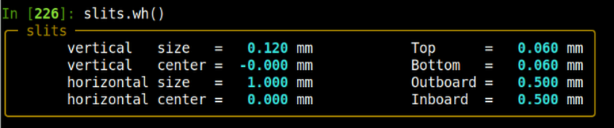
Fig. 2.1 The slit positions report#
2.3. Attenuator#
The attenuator box is implemented as an actuator in Bluesky. This
means it’s setting can be changed with the mv() command:
RE(mv(attenuator, 3))
where the target position is the binary representation of the attenuator foils. In this example, position 3 means that foils #1 and #2 are in the beam path.
As there are four foils in the attenuator holder of thicknesses 1, 2, 4, and 8. So, valid positions are any integer between 0 and 15, inclusive.
This implementation allows the attenuator setting to be hinted, thus reportable like any motor axis or scalar. It can show up in the best-effort callback table printed to the screen, it can be a record of a measurement, it can be written to an output file or included in a plot.
You can get the current numerical value of the attenuator by:
attenuator.attenuation.position
You can get a report about the attenuator status written to the screen with:
attenuator.wh()
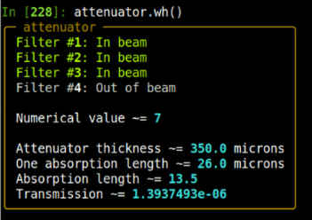
Fig. 2.2 The attenuator status report#
2.4. Goniometer table#
The goniometer table physical and pseudo motors:
pseudo motor |
purpose |
|---|---|
|
vertical motion |
|
horizontal motion |
|
pitch (rotation about X) |
|
roll (rotation about Z) |
|
yaw (rotation about Y) |
physical motor |
purpose |
|---|---|
|
upstream outboard Y jack |
|
upstream inboard Y jack |
|
downstream Y jack |
|
upstream X slide |
|
downstream X slide |
Both physical and pseudo motors can be moved using standard movement plans, e.g.:
RE(mvr(table.vertical, 0.2))
RE(mv(table.yuo, 4.41))
The position of a physical or pseudo motor can be found, for example, by:
table.lateral.position
table.yd.position
The positions of the table motors and pseudomotors can be seen with
table.wh()
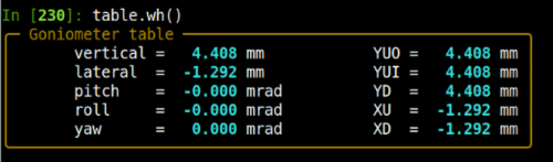
Fig. 2.3 The table position report#
2.5. Photon delivery system#
Full control over the photon delivery system is given using the same code as is used for the XAS end station. While and experiment performed a the standard energy of 8.6 keV probably won’t need to touch the photon delivery system, the are several situations where this might be helpful, for example:
adjust the yaw or bend of the focusing mirror
change to a different energy
adjust either the post-mono or hutch slits
retune the pitch of the monochromator
2.5.1. Shutters#
- Open and close the photon shutter
In the nomenclature of BMM, the photon shutter is
shb. Open and close this shutter with:shb.open() shb.close()
These plans are somewhat more elaborate than simply toggling the state of the shutters. It happens from time to time that the shutter does not trigger when told to open or close. So, these plans try up to three times to open or close the photon shutter, with a 1.5 second pause between attempts.
If you wish to open or close the photon shutter (using the same multiple attempt algorithm) in a plan, do:
yield from shb.open_plan()
yield from shb.close_plan()
- Open and close the safety shutter
This is the front-end shutter. Closing it takes light off the monochromator, which is not something you typically want to do during an experiment. That said, the safety shutter is
shain the BMM nomenclature:sha.open() sha.close()
and:
yield from sha.open_plan()
yield from sha.close_plan()
2.5.2. Monochromator#
Todo
show dcm report, explain how to change energy, tabulate dcm motor names
2.5.3. Focusing mirror#
The focusing mirror is driven to the correct location when setting up for XRD operations. That said, adjustments to the mirror might be needed to optimize the beam delivery to the goniometer. For example, adjustments to the yaw, e.g.:
RE(mvr(m2.yaw, 0.01))
can fine tune the orientation of the focused beam such that the axes of the elliptical beam shape are parallel to the goniometer slit blades.
Adjusting the bender can be used to optimize the vertical focus of the beam, e.g.:
RE(mvr(m2.bender, 5000))
Adjusting the pitch of M2 can be used along with the bender to optimize the horizontal focus, e.g.:
RE(mvr(m2.pitch, 0.01))
although the horizontal beam size will always be large than the vertical.
The positions of the focusing mirror motors and pseudomotors can be seen with
m2.wh()
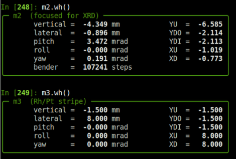
Fig. 2.4 The position reports for the focusing and harmonic rejection mirrors#
2.5.4. Harmonic rejection mirror#
The harmonic rejection mirror is not used at 8.6 keV, nor at any energy above 8 keV.
It would be needed for any energy below 8 keV, but the goniometer has never been commissioned for operations below 8 keV. Doing so would be a significant project. It is not known if the table jacks have enough range of motion to accommodate lower energies.
The positions of the harmonic rejection mirror motors and pseudomotors can be seen with
m3.wh()
as shown in Figure 2.4.
2.5.5. Post-mono and hutch Slits#
For XRD operations, the standard setting of the upstream slits are 18 mm by 1.3 mm for the post-mono slits and 7 mm by 1 mm for the hutch slits. The goniometer slits are used to clean up the incident beam in a way that is approriate for the scattering experiment.
The positions of the post-mono and hutch slits can be seen with:
slits2.wh()
slits3.wh()
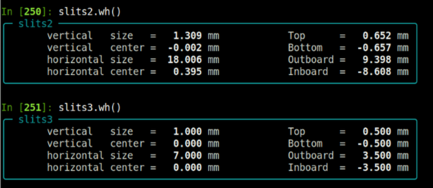
Fig. 2.5 The position reports for the post-mono and hutch slits#